Wednesday, January 9, 2008

Energy Efficient Housing Construction: Heating

Heating Systems


An energy efficient home by definition has very little heat loss because of high insulation levels and airtight construction. This leads to two problems: finding a properly-sized heat source and providing adequate ventilation to maintain indoor air quality.


Except for extremely cold periods, a properly designed and constructed energy efficient home can sometimes gain almost enough daily heat from 'waste' sources such as the heat given off by lights, people and appliances. During sunny, cold days solar energy gains also contribute to reducing the heating load. These heat sources are often called 'internal gains'.


Modern control systems such as programmable thermostats can further help to reduce heating energy consumption.


Sizing the Heating System


Heating equipment in a home must be capable of maintaining an interior temperature of 68 to 72° F (20 to 22°) during the heating season. Heating equipment is generally oversized for most homes, but is even worse if the home is an energy efficient home. This leads to frequent on/off operation reducing both efficiency of fuel use and service life of heating equipment.


A heat loss calculation is required to determine the heating system required. It should have a capacity of no more than 10% in excess of the calculated requirement. Installing the smallest capacity heating equipment to meet the loads will save both energy and money. Calculation of total home heat loss is generally done by heating contractors. Contractors inexperienced in understanding low energy house design and heat loss, however, may still result in drastic over sizing. A simple heat loss calculation method is provided in this section.


Isolating The Heating System


If a fuel burning furnace, boiler and/or hot water heater is required, building an airtight enclosure (mechanical room) around the appliances can help control chimney heat loss. Separate combustion and fresh air supplies feed into this room. No previously heated air is used by the fuel burning appliances and cold outside air is prevented from entering other areas of the home. This isolated room must be insulated and sealed from the rest of the home. Water pipes and heat supply ducts should also be insulated.
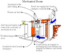


Isolating The Heating System

Calculating Heat Loss


Calculating the heat loss from a home is quite simple. The heating requirement will be highest when the outside temperature is lowest and there is no solar gain. A cold winter night is when the heating load will be greatest. Heat flows out through all the building surfaces including walls, ceilings, floors, windows and doors.
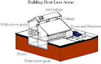


Building Heat Loss Areas

Heat loss through each surface can be calculated using the following equation:


Heat Loss Formula

Heat is also lost through infiltration and exfiltration - air leakage. This heat loss can be calculated using:


Air Leakage Formula

Note: change the constant 0.36 to 0.018 Imperial units.


There are also a number of sources of heat gain in a typical house. Not only do the occupants give off heat, appliances and lights contribute significantly to home heating. Each person can provide about 75 watts of heating energy while 200 or 300 watts are available from appliances (like freezers, ranges, refrigerators, etc). The average home therefore provides 500 or more watts daily of the total energy required for space heating.


An example heat loss calculation is shown using Plan 13 from Energy Efficient House Plans post. Plan 13 is a 1,920 square foot (178 sq. metres) two level, rectangular bungalow. If this house was to be built in the Red Deer (Alberta, Canada) area, the outside heating design day temperature is - 26° F (-33° C). A common inside temperature is 68° F (20° C) - the difference between them is 94° F (53° C). Design day temperatures and heating degree days information for your locale is usually available from your local weather office. A short list is provided as an example of January design temperatures and degree days for various Canadian cities.


The first set of equations is used to calculate the heat loss from each of the seven surfaces (substitute the areas, R-values and the temperature difference for each surface from your plan). The air leakage heat loss is next calculated using the second equation. The building air volume is 16,775 cubic feet (475 cubic metres) and an air change rate of one-third (1/3 of the house air is replaced every hour with fresh air) can be used in the equation (a typical rate for a well-built, energy efficient home). Substitute the house volume from your plan into the equation. Using the same temperature difference, the total air leakage heat loss is calculated and added to the surface heat loss figures. Subtracting the heat gain average of 500 W results in a total space heat requirement of 8200 W for this example (8.2 kW or about 28,000 btu/hr).


There are a wide variety of computer software programs available which can be used to more accurately calculate building heat loss. These programs require a detailed breakdown of each building component and complete area weather data. Most of the programs available require a considerable learning curve and are often not practical unless you do a lot of heat loss calculations, are a house designer or are designing a complex solar building.


The efficiency of the heat source must be taken into account when selecting it. In the example, an 8.2 kW heat source would be needed (28,000 btu/hr). If one chooses a 100% efficient electric heating source, the exact figure calculated above can be used to size equipment. Gas furnaces range from 70% to 80% efficient (measured seasonally - over an entire year of operation). Divide the heat load (8.2kW) by the system efficiency (0.70) to obtain the 'bonnet' size of 11.7kW (40,000 btu/hr) necessary to provide 8.2kW. Gas-fired furnace and boiler units with efficiencies of 90% to 95% are also available but are usually produced in large output sizes and are more expensive.


Heating Systems - Forced Air


Forced Air Distribution Systems


Homes incorporating forced-air heating systems are very efficient at distributing heat around a home, preventing stagnation of air and moving heat from different sources to the overall space. They also work well with mechanical ventilation systems. The central heat source could be a fuel-fired furnace. Unfortunately the smallest sizes usually available are in the 50 to 60,000 Btu/hr range (18 kW ) and this heating capacity is often much too large for an energy-efficient home. Using such a large heat source is inefficient in terms of fuel consumption. For example, a 50% oversized furnace will use 20% more fuel in heating the same space than a correctly sized unit.


Forced-Air Heating System

Good heat distribution, air movement, filtering capability, humidity control and low maintenance are some of the advantages with a properly designed and installed forced-air heating system.


A forced-air distribution system works well if a home receives abundant solar energy. Since passively heated spaces can easily overheat when the window area is too large or if there is not enough mass to absorb and store the solar energy, having continuously circulating air with the forced-air distribution fan running at a slow speed helps prevent overheating. Passively heated air is distributed to all the spaces in the home, not just those on the south side.


High Efficiency Gas Furnace


High efficiency (condensing) forced-air gas furnaces offer efficiencies of 90% or better. These units use electronic ignition, induced draft fans and condensing heat exchangers. Ductwork and installation is similar to a standard furnace with the exception of the chimney and condensate drain. Condensing furnaces require a drain pipe connected to a floor drain to allow condensation (water) from the heat exchanger to drain. A standard chimney is not required because the exhaust air temperature is reduced to the point that high temp plastic pipe can be used as an exhaust vent out of a side wall.


The diagram shows a fresh air duct from outside, ducted directly into the cold air return. Combustion air is separately ducted from the exterior to the front of the furnace. Note that both air ducts are insulated. Although not shown, an air to air heat exchanger should be installed to maintain indoor air quality.


High Efficiency Furnace

Radiator (Fan Coil Unit)


A good heating solution for an energy-efficient house is to use the advantages of a forced air system (such as good air and heat distribution, filtering capability, low maintenance) and add a small auxiliary heat source to it. This could be an electric heating element, a hot water heated coil unit, a heat pump or simply a separate wood or electric unit providing heat that the system picks up and distributes via the forced air system.


This example shows how hot water heating can be combined with a forced air system. Hot water from a boiler is circulated through a radiator placed in the ducting of a forced air system. A fan forces the air through the radiator where the heat is picked up and distributed to the entire house. The duct work design is the same as any forced air system.


An air to air heat exchanger helps to maintain indoor air quality by suppling pre-heated fresh air to the cold air return, which is then distributed to the rest of the house by the forced air system.


Fan Coil Unit


Heating Systems - Hydonic Systems


Hydronic Heating Systems


Hot water (hydronic) heating systems usually consists of a boiler and a heat distribution system. This distribution system shows baseboard radiators. A wide variety of radiator types are available. Hot water is supplied directly to the radiators and returns to the boiler by way of a separate line. An expansion tank provides a cushion of air for heated water to expand into if pressure builds up in the system. An insulated fresh air duct provides combustion air directly to the boiler.


Because hydronic systems have no air movement an air to air heat exchanger is used to maintain indoor air quality and transfer heat from the exhaust air to the incoming fresh air supply. Fresh air is supplied (individual ducts) to each room while exhaust air is removed from the kitchen, bathrooms, hallways and laundry rooms. Two separate ducts (intake and exhaust) are installed through the floor header area and must be at least 12 feet (4 m) apart to prevent cross-contamination.
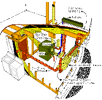


Hydronic Heating System

Radiant Floor Heating Systems


Radiant floor hot water heating systems work well in an energy efficient home. Hot water is distributed through water pipes installed in the floor. The layout and distribution of pipes is determined by the building heating requirements. Insulation is necessary under basement floors to help reduce heat loss to the surrounding earth. A reflective material and Insulation are recommended for all floors to maintain heat transfer in the desired direction (usually upward).


With this type of heating system, a balanced mechanical ventilation system which exhausts stale air and supplies fresh air separately (preferably to every room) is essential to maintain indoor air quality. Air to air heat exchangers (also called 'Heat Recovery Ventilators') are recommended for energy efficient homes.


Radiant Floor Heating


Heating Systems - Other Systems


Electric Systems


Since chimneys are a source of air leakage, electrical heating systems have merit in that no chimney is required. Although electricity is a higher priced fuel, its increased efficiency and minimal capital cost combined with the small required output in an energy efficient home make it a potential alternative.


This system uses an electric heating element placed in a forced air system This combines the benefits of forced air and a small heating system to match the heating load of an energy efficient house. There are also a number of radiant electric (ceiling or floor) panel systems available for home heating.


Fresh air from the heat exchanger is distributed throughout the house by the forced air system.


Electric Heating

Heat Pumps


Heat pumps transfer heat by circulating a refrigerant (gas) through an evaporation- condensation cycle, similar to a refrigerator. Winter heating and summer cooling are both handled by a single system. Heat pumps can operate using water, ground or air as the heat source. These systems use electricity to extract heat and under normal operating conditions will produce at least three times more heat energy (or cooling) than they use in electrical energy.


This diagram shows an air to air heat pump system with forced air delivery. During the winter cycle, heat is extracted from the outside air and released into the house. In summer, heat is extracted from air inside the house and dumped outside, thereby cooling the house. One potential problem with air base heat pump systems is that they use more energy than they produce if outside air temperatures drop below 50° (10°).


Heat Pumps

Combined Systems


Combined systems are now being offered which provide both space heating and domestic hot water. Systems are available which use fossil fuels, heat pumps or electric resistance heating sources to provide domestic hot water and space heating from one unit. Available with smaller output ranges these units should work well with an energy efficient home.

Energy Efficient Housing Construction: Roof and and Ceilings

Roof Construction


Most homes built in cold climates have a sloped roof surface while the interior ceiling can reflect the roof slope, follow a different slope, or can be flat. Because heated air does tend to rise, the recommended insulation levels for ceilings is usually higher than for walls. A complete, well-sealed air/vapour barrier is essential at the ceiling level, but because of light fixtures, plumbing vents and chimneys, can be difficult to install. The air/vapour barrier must be sealed around the potential 'holes' in a ceiling, regardless of the type of roof or ceiling construction. The obvious first step in design is to eliminate as many of these potential problems as possible before they occur in construction.


Air Sealing


The electrical wiring, the various junction boxes, and ceiling outlets create numerous opportunities for breaks in an otherwise continuous ceiling air/vapour barrier. Much can be done to eliminate some of these potential breaks. Using interior wall-mounted fixtures are examples of alternatives. If wiring and outlets are required in the ceiling, using special polyethylene air/vapour boxes or isolating the air/vapour barrier are methods which can be used to maintain the continuity of the air/vapour barrier.


Ceiling Air/Vapour Barrier Protection

Exhaust Fan Venting

Ceiling mounted exhaust fan installations also cause problems. Firstly, because of the difficulty in sealing around them and secondly because the built-in dampers do not seal well and let warm air leak out. They usually vent through the attic so leaking warm air can cause condensation problems.


If possible, exhaust fans should only be installed on interior walls with ducts routed down the wall and out the floor joist space. This prevents cold air from infiltrating in through the duct pipes.


Plumbing stacks and chimneys are necessary 'punctures' in the ceiling of a home. The ceiling air/vapour barrier can be well sealed to plumbing stacks and vents but the pipes must be securely fastened so that expansion and contraction does not break the seal. An expansion joint, placed in the warm interior, can accommodate pipe movement so that it does not affect the ceiling joint.


Sealing Plumbing Stacks and Chimneys


Air/Vapour Barrier Around Plumbing Stack

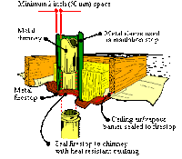
Air/Vapour Barrier Around Chimneys

Metal firestops, properly insulated and sealed are needed to control air leakage around chimneys. Again, by making the proper design decisions, the number of stacks, vents and chimneys may be reduced.


Many homes have an exterior door in their ceiling - an attic access hatch. It is best if the hatch is eliminated from the interior and placed on an outside gable end or through an unheated garage if possible. If not, make sure that the attic hatch door is well insulated, weatherstripped and secured to eliminate air leakage and heat loss.


Roofs and Ceilings


Flat Ceilings


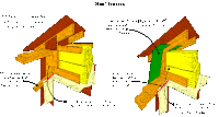
The use of flat ceilings and truss rafters is a common North American building practice. This type of construction leaves an adequate depth in the attic space for loose fill or batt insulation except at the edge over the exterior walls. Modified types of truss rafters can be used to increase the depth at this point.


Roof Trusses

Maintaining adequate attic ventilation is important. For every 300 ft² of ceiling area, there must be 1 ft² of free ventilation area provided by soffit and roof or gable end vents (a 300:1 ratio - 300 m² of ceiling area vented by 1 m² of vent). This ventilation ensures any water vapour that does find its way above the insulation will be carried out of the space.


Interior Partitions

Using truss rafters allows the ceiling air/vapour barrier to be installed in one piece. Because the trusses span from exterior wall to exterior wall, the interior partitions can be installed after the ceiling is sealed and covered. However, if partitions must be installed before the ceiling polyethylene is applied, an extra air/vapour barrier strip has to be added to maintain continuity. Any joints must be sealed and must occur over solid backing such as ceiling joists or partition wall top plates. Isolating the air/vapour barrier with strapping is an option which provides protection against tears and provides a space for electrical wiring installation.


Sloped Ceilings


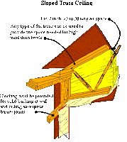
There are three methods of building well-insulated and sealed sloped ceilings. One method is to incorporate a wide joist or flat truss which will leave sufficient space for the insulation and ventilation.


Sloped Truss Ceiling

Sloped Truss Ceilings


Another method used for sloped ceilings is to use a scissor truss, which has a flatter bottom slope than top. This type of ceiling is then insulated and sealed in the same method as was discussed for 'Flat Ceilings'. To attain an R-40 value ( RSI-7) a minimum depth of at least 16 inches (400 mm) is required.


Scissor Truss

Strapped Sloped Joist Ceiling


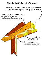
Strapping the ceiling is the third way of providing a good ceiling insulation level. An isolated air/vapour barrier results. This construction method utilizes 2 x 12 inch (38 x 286 mm) roof joists. At least two thirds of the insulation value must be outside the polyethylene air/vapour barrier.


Sloped Joist Ceiling

Energy Efficient Housing Construction: Windows

Window Design


Windows serve a variety of purposes, they are one of the most prominent architectural aspects, can provide ventilation and have a great impact on the energy efficiency and comfort levels of a home. Windows can account for 30 to 40% of the heat loss or heat gain in an energy efficient home.


Window in Winter

The overall energy performance of a window unit in a cold climate depends on the glazing (glass or sealed unit), window style or type, frame and sash materials, air leakage, installation and the use of interior coverings or exterior shading devices. Window orientation also plays a large roll in overall window performance due to the combined effects of solar gains, seasonal winds and shading factors. Views, ventilating, natural lighting and passive solar aspects as well as architectural and aesthetic values must be considered. Window types and placement depends on which combination of functions the window must satisfy.


Window selection and placement are key design considerations which effect home energy usage and lighting, as well as comfort and humidity levels. Successful designs usually exhibit a minimal total window area with the majority oriented south for passive solar gain. If possible plan spaces so that most windows face south, while few windows face east or west, and very few, if any at all, face north.


South-facing glass area should not exceed 8 to 12% of the total living area on an energy-efficient home unless new high performance units are used and precautions are taken to avoid potential overheating problems. Opening windows can help control overheating on sunny spring or fall days. If high performance window units are used the total glass area could be increased to 10% or 15% without increasing the overheating potential. Different window sizing rules need to be applied when dealing with increased internal mass, attached sunspaces or mass walls.


Fading, sun rot and damage to finishing materials are problems which can be caused by large areas of south or west facing windows. Low-E window units can reduce the UV portion of sunlight that causes the damage by 60 to 90% while still admitting visible light. One should also select materials such as wood, masonry or special fabrics which will not deteriorate from exposure to direct sunlight. Using a masonry material for floors or walls is an especially good choice since it provides some heat retaining thermal mass as well as being a durable interior finishing material. Framing members may have to be increased in size or number to carry the weight of a masonry floor or wall.


Although living spaces on the south with large windows capture valuable solar energy, there may be times when that heat and glare is undesirable. High performance Low-E units can be used to reduce solar gains and glare from large south or west facing windows.


Window Placement

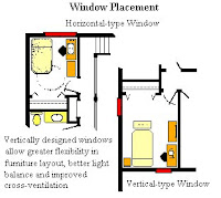
Vertically designed windows can create a pleasing indoor feeling in terms of natural lighting, viewing and providing ventilation. In bedrooms, furniture placement is often improved with vertical windows. Vertical windows can simply be described as units which are taller than they are wide. On the other hand, it is often difficult to place furniture (like beds or seating units) under vertically designed windows. Because the sills are 32 inches (800 mm) or more above the floor, horizontal windows can be hard for children to open, view out of, or use as an emergency escape.


Adding windows to a side wall or using clerestory windows are two ways illustrated for balancing the natural light. In addition, clerestory windows can bring natural light deep into a building - north side rooms with no other windows, for example. Skylights work well for natural lighting but can cause problems in cold climates. Light pipes or tubes offer a new option for providing day lighting in cold climate homes.


Balancing Natural Light

Window Coverings


Interior and exterior window coverings can be used to provide control against overheating and night time heat loss. Louvred horizontal or vertical blinds, shutters or awnings are devices which can be utilized - either on the outside or inside to block the sun. Screening devices used on the outside are more efficient at blocking incoming energy but can be difficult to operate in the winter. Movable window insulation can also be used to help control heat losses. In addition to lowering heat losses, window insulation can function as the window covering (eliminating the need for drapes), control heat gain in the summer, provide privacy and protection and reduce convective drafts near windows. Swinging or rolling shutters, thermal curtains or shades and between-the-glazing insulations are some of the types commercially available.


Window Shading Devices

Window Units


When shopping for window units look for high performance windows which have high tested unit R (RSI) values. Units must offer good durability and materials, while meeting your design and budget requirements. Current window units offer a variety of new technologies and thermal improvements to reduce heat loss and condensation problems.


High Performance Windows


  • Low-emissivity - Low-E coatings applied to interior (or exterior) glazing surfaces which reduce the radiant heat losses and can be used to control solar gains.
  • Insulating, inert gases (like Argon or Krypton) between the window panes reduce convection heat losses.
  • New insulating spacers and low-profile insulating frames combined with better air sealing on opening units, have improved solar gain while reducing air leakage and conduction heat losses.
  • Low-E coated films made of thin polyester or plastic between two panes of glass provide lighter weight, high performance, multiple-glazing units.


Window Types


Fixed window units are large expanses of glazing primarily for viewing through. The frame and the sash are both fixed in place, do not open and may have multiple glazings. Fixed units are the most energy efficient.


Horizontal Sliders come in several combinations. Choose ones with a fixed window on one side and a sliding window on the other, much like a patio door. The window segments may have double, triple or high performance glazing units incorporated into the design. Units are difficult to weatherstrip effectively, subject to air leakage and are not recommended for energy efficient homes.


Casement windows operate much like a door. They have side mounted hinges, a hand crank which opens the window and pivot on a vertical axis. Some units have a hand crank that swings the window open and then slides the window to the centre of the opening. Two hatch-levers on the sash lock the window to the frame, pulling it tight against the weatherstripping and provide good security. These windows are the easiest to weatherstrip effectively and are consequently the most draft free of opening windows.


Awning windows are very similar to casement windows except they open to the outside from a hinge along the top. They are very weather tight, provide good security and can be compared to a casement in overall energy efficiency.


Tilt and turn windows have special hardware that allows the window to tilt in at the top or to open like a door, toward the inside. These windows are also very weather tight, comparable to awning or casement in energy efficiency with a locking type handle and good security.


Pivoting windows are common in Europe. They pivot in the centre of the frame in a vertical or horizontal axis depending on the model. Moderately airtight, this window type is not a good choice in 'buggy' climates as it is difficult to screen effectively.


Bay or Bow windows are extremely popular. They are windows that jut out on a cantilever floor section, with a series of fixed or opening units joined together in a 3 window or 5 window configuration. Care must be taken to ensure that proper insulation and vapour barrier techniques are applied to the floor area or condensation, drafts and cold floors may occur.


Combination windows are simply an amalgamation of several different units such as fixed units and casement windows. These usually come pre-assembled from the factory ready for installation.


Skylights


Good quality skylights can be an asset to any home during a long indoor winter. In cold climates, choice and placement of skylights has to be done carefully in order to avoid overheating and sun damage during the summer and excessive heat loss with dripping condensation in the winter. Skylights can on the other hand provide a view of cloud scapes and sky, while allowing light deeper into the home than wall mounted windows can, especially on cloudy days.


Glazings for skylights are available in acrylic, polycarbonate, polystyrene and glass. The requirements for a skylight unit should be at least the same as those for a high performance window unit or better.


The deeper the well of the skylight, the less air circulation and the greater the potential for condensation. Flaring the well at the bottom of the shaft will increase air circulation and the amount of light being delivered by the skylight. Sealing a piece of glazing at the ceiling opening of the skylight well can also help. The light well that frames the skylight should be finished in a light colored paint or mirror to allow the well to reflect the maximum amount of light.


When choosing a skylight consider the slope of the roof in relation to the shape of the skylight. Flat skylights on a low slope roof tend to collect snow and dust more readily than dome or pyramidal shaped skylights. Opening skylights can vent hot air out of a house rapidly but may need regular maintenance in order to seal effectively when they are closed. Also, opening skylights should be equipped with a screen.


When placing a skylight on your home, southern or western exposures should use glazing which is tinted, or has a Low-E coating that blocks at least 50% of the solar gain and 90% of the ultra violet light. Consider the percentage of roof area that skylights will cover in any one room. Skylights are usually poor insulators and large areas of roof glazing can be a source of cold drafts and condensation problems on long January days and nights.


Exterior Doors


Energy efficient exterior doors should have an insulated core bonded to the inside and outside skins of steel alloy, aluminum, fibreglass or wood composite. For cold climates insulated doors are a good choice. With much higher insulating values (R-10, RSI 1.8) insulated doors are less prone to warping and are easier to weatherstrip effectively. A door may also have one or two 'side lites' of glass which should be high performance glazing units. Metal doors should have good quality compressible, magnetic or adjustable weatherstripping to reduce air leakage.


Patio Doors


Patio doors can be the largest window in your house. All the components that make a good high performance window also make a good patio door. Triple glazing is very seldom found in a patio door as it is heavy and requires a very thick unit. Some patio doors have two sliding panels while others have one panel fixed and one panel that slides. Sliding doors are very difficult to weatherstrip. Friction and foot traffic wear the weatherstripping out in short order. Rollers can also wear out, requiring replacement. A better type of sliding patio door is available that operates like an airplane door - popping in and sliding away from the weatherstrip with a latching type handle.


Garden, Terrace or French doors are a better choice for energy efficient homes than traditional sliding patio doors. These are similar to double entry doors, with a large glazing area, and one or both opening inwards. Units are available with insulated cores, high performance glazings and can be weatherstripped very effectively. Screens attach to the inside or are mounted on a track on the outside.


When designing a new home take into consideration the location of patio doors. Avoid northern exposures and prevailing winds. Good installation is also critical. Poor installation can cause poorly operating doors, drafts and increased condensation problems.

Energy Efficient Housing Construction: Exterior Walls

Exterior Walls


This section describes types of wall construction and how walls are connected to the floor, ceiling and foundation construction to maintain airtightness and high levels of insulation. The major obstacles to well-insulated and sealed walls are the necessary penetrations in the wall such as doors, windows and electrical outlets. Again eliminating as many potential problems as possible in the design stages is the first step - place wall switches on interior partitions, locate exhaust fans on interior walls, use the most energy efficient windows and doors possible.


Since there does need to be some electrical outlets on exterior walls, they can be installed using polyethylene air/vapour boxes for wall outlets. Some of the wall details show an isolated air/vapour barrier so that electrical wiring can be installed inside the polyethylene layer. Floor or baseboard outlet systems can also be used to eliminate the problem of outlets on exterior walls.


Wall Penetrations


Window or Door Installation

The rough opening space left around installed doors and windows creates a special sealing and insulating problem on exterior walls. Always use good quality window and door units to minimize air leakage heat losses through the unit. They must however also be installed properly to eliminate air leakage around the units. An air/vapour barrier strip can first be sealed (caulked) and attached (stapled) around the outside of the door or window frame. Once the unit is installed the cavity between the rough opening and the window frame is then insulated. This strip is then attached and sealed to the wall air/vapour barrier to create an airtight seal around the opening.


Single Stud Walls


Single Stud Wall Detail

The use of a single stud width for exterior walls is the most common form of North American residential construction. To obtain an R 20 rating (RSI 3.5) in a single stud cavity, 2 x 6 inch (38 x 140 mm) construction must be used. This is an absolute minimum wall R-value level for energy efficient housing. To maintain air/vapour barrier continuity from lower to upper floors, the polyethylene air/vapour barrier can be carried around the floor joists during the early stages of construction. If extra exterior or interior insulation is not being added the walls should be offset 2 inches (38 mm) over the edge of the subfloor so that a piece of rigid insulation can be added to the outside of the joist space (required to keep the air/vapour barrier on the inside of the insulation). Box beam lintels can be made of plywood and are one way to increase the insulation through lintels over windows and doors. Installing rigid insulation between header plates is another method.


Exterior Insulation


In an effort to provide more insulation (as well as blocking the thermal bridges through the wall studs, plates and lintels), an insulated sheathing of rigid fibreglass or rigid foam can be applied to the outside of the wall. This provides a 'blanket' over the wall with more insulation applied over lintels, double studs, corners and the joist space. As well, the sheathing layer can extend down to join the foundation covering. Window and door jamb extensions must be used when wall thicknesses are increased.


Exterior Insulated Sheathing

Interior Insulation


Interior strapping is another method of increasing wall insulation in single stud construction and reducing the thermal conduction through the wall studs. This method isolates the air/vapour barrier in the wall and provides a convenient cavity so that the polyethylene is not punctured for wiring or plumbing. Strapping is placed horizontally across the wall studs which works well with horizontal wallboard application. The wall air/vapour barrier must be sealed to the ceiling (or second floor), floor and foundation polyethylene layers as shown. At least two-thirds of the insulation must be outside the polyethylene air/vapour barrier.


Interior Wall Strapping

Staggered Stud Walls


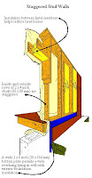
A method of increasing wall insulation levels in a single cavity is to use wider plates. Since wide studs would create more of a thermal bridge, a staggered stud wall can be used instead. A good example would be using 2 x 4 inch studs (38 x 89 mm) on 2 x 8 inch plates ( 38 x 184 mm) to create an R 28 (RSI-5) wall. Even wider plates can be used to obtain higher RSI-values. A staggered stud wall does offer benefits in terms of joist space for insulation, but the air/vapour barrier is on the inside where it can be easily damaged.


Staggered Stud Wall Details

Double Wall Technique


This wall construction method was developed both to provide a wide wall cavity for high levels of insulation and so the air/vapour barrier could be isolated inside the assembly in a protected position. Two individual stud walls are constructed. The inside one, usually 2 x 4 inch (38 x 89 mm), is the structural wall and is complete with double plates, window lintels and outside sheathing. The air/vapour barrier is placed under the outside sheathing on the outside of this structural wall.


A second stud wall is placed some distance out from the structural wall - its function to provide support for the exterior finishing material. Insulation is placed in the resultant three cavities. The amount of insulation depends on the width of each cavity but there must be at least two-thirds of the total wall insulation value outside the sheathing (so that the air/vapour barrier is in the correct position).


Plywood spacers at the plates can be used to position the outer wall. If a 4 inch (100mm) cavity is left between two 2 x 4 inch (38 x 89mm) stud walls, then three layers of R-12 (RSI 2.1) insulation can be used to give a total value of R-36 (RSI 6.3). Leaving 6 inches (150mm) between the walls would result in R-44 value (RSI-7.7) being the wall total - with R-32 (RSI 5.6) on the outside of the polyethylene layer.


The double wall construction method will result in a home that is super insulated and sealed The single biggest disadvantage for double wall construction is the associated cost increase in materials and labour.


Wall Systems


A variety of wall systems are now widely available which utilize expanded-polystyrene panels combined with wood, steel or concrete structural members. Most of these wall systems derive their structural strength from integral wood or steel framing members embedded inside the insulation panels. These systems use factory built wall sections ready to be erected on site, and are available in R-20 to R-40 (RSI 3.5 to 7.0) values. Comparable roof panels are available up to R-40 (RSI 7.0). Foundation wall panels are also available which use preserved wood and sheathing or steel instead of regular wood as the structural members. A number of manufacturers offer concrete (block type) wall systems for both foundation and above grade walls with rigid insulation inserts.


Engineered structural sandwich panels (often called stressed-skin panels) are also available from a number of manufacturers. Panels generally have a pre-finished interior and exterior membrane enclosing a urethane, polystyrene or other foam core. The skins are typically made of oriented strand board (OSB), wafer board or plywood and some are available with interior surfaces pre-drywalled. Standard wall panels are available in R-20 to R-40 ( RSI 3.5 to 7.0) with roof panels up to R-60 (RSI 10.5).

Energy Efficient Housing Construction: Foundation

INTRODUCTION


This section is designed as a guide to understanding, energy efficient house construction. The Canadian 'House as a System' planning approach was used. This approach ensures that all of the components which make up the home function well together.


Energy efficient housing is not any particular housing style or type, almost any housing can be built using energy efficient construction techniques. Improvements in design and construction which lower energy use are permanent and are one-time-only costs which increase the value of your home, while lowering the ongoing operating costs.


Energy efficient housing in simple terms is 'housing which uses the energy put into it as efficiently as possible'. It is not difficult to plan and build energy efficient housing. Using existing techniques and materials, total home energy usage can be reduced by 60% to 80%.


The extra costs for upgraded materials, construction, insulation and airtightness required for energy efficient housing should only add 5% to 10% to the total building cost. With potential savings of 60% to 80% on energy costs, the simple payback period may only be 5 to 8 years at current energy costs. Simple payback is calculated by dividing the increased building cost by the yearly energy cost savings.


Faced with today's ever increasing cost of energy, and concern over what future energy costs will be, building energy efficient housing makes more economic sense now than ever. Energy efficient housing uses less energy and therefore produces less pollutants, this is one area where each of us can help preserve the environment for future generations.


Energy Efficient Construction


The basic shell construction assemblies of a home - foundation, walls, floors and roofs - are covered in detail in this section. Standard house building practices are illustrated with the emphasis on high insulation levels and a continuous air/vapour barrier installation. Details include how the floor, wall and ceiling assemblies join (and the sealing problems created) and how airtightness and insulation levels are maintained in spite of obstructions such as windows, doors, wiring, plumbing, pipes, or chimneys. The object is not to cover all aspects of structural building design - only how energy efficient construction can be incorporated into existing residential construction practices.For reference, Table 2 lists metric building material sizes along with Imperial equivalents.


Controlling Heat Loss


Most important to the success of an energy efficient home is the quality of construction. Even poorly sited homes (as often occurs in urban areas), with little passive solar gain potential, can be very energy efficient homes. Adequate levels of insulation and careful sealing can combine to cut heat losses so that the energy required for space heating will only be 15% to 25% of a 'normally' constructed home.


Home Heat Loss


A good way to think about a house is to consider it a 'shell' which must keep heat inside during the winter. This shell is made up of floors, ceilings and walls constructed with various building materials. Heat is lost from the inside of your home in two ways: either directly through the shell or when warm indoor air leaks out through cracks and holes (replaced by cold outside air leaking in).


Energy loss through the building shell can be 40% to 70% of the total and is controlled with insulation. Air leakage losses account for the remainder and is controlled by the air/vapour barrier, weatherstripping and caulking.


Insulation


Insulation is measured by its R-value (or RSI-value). The higher the R-value, the better the insulation stops heat flow. R-values for different building materials are given in Table 1. The total R-value for a wall, ceiling or floor is the sum of the values of each part or layer.


Calculating R-Values


For an Energy Efficient House in a cold climate (5000 heating degree days or less), the recommended R-values (RSI-values) are:


  • R-10 (RSI 1.7) under foundation floor.
  • R-30 (RSI 5.0) for above grade floors such as overhangs, cantilevers and below projecting windows.
  • R-20 (RSI 3.5) for all walls above and below grade.
  • R-40 (RSI 7.0) for all ceilings whether sloped or flat.


For a Super Energy Efficient House in a cold climate or if building in a very cold climate (5700 heating degree days or more), the recommended R-values (RSI-values) are:


  • R-30 (RSI 5.3) for all foundation walls.
  • R--36 (RSI 6.3) for all walls above grade.
  • R-40 (RSI 7.0) for above grade floors such as overhangs, cantilevers and below projecting windows.
  • R-60 (RSI 10.5) for all ceilings whether sloped or flat.


Most insulation products can be placed in one of three types - blanket, loose fill or rigid.


Blanket Insulation (often called 'batt') is the easiest to handle and being premanufactured, has a consistent quality. It is most suitable for application to vertical cavities (as in walls). There are two common kinds, glass fibre and mineral fibre, both with an R-value of about R-3.5 per inch (RSI-value 0.024 per millimetre)


Loose Fill Insulations are made from a variety of products and all work well for horizontal surfaces such as ceilings where the depth is not a problem. They can also be used in regular or irregular joist and wall cavities. It is essential that loose fill materials made of wood or paper products be treated for fire resistance. R-values range from R 2.5 to 3.5 per inch (RSI-values 0.016 to 0.024 per millimetre of thickness).


Rigid Insulations are made of a number of products such as polystyrene, fibreglass, urethane or isocyanurate. They are the most expensive types but do offer the highest R-values up to R-7.5 per inch (RSI-values to 0.051 per millimetre). Rigid insulations are a fire hazard when exposed to the interior but are considered safe when installed properly. In particular, they can be used on the interior of a home if covered by at least 1/2 inch (12 mm) of drywall or plaster which is mechanically fastened to the structure. Rigid insulations can be used on the outside of concrete, masonry or wood walls and under siding or stucco finishes. Some high density types are suitable for use under concrete floor slabs.


Spray-Foamed Insulations are mixed on the job site by the contractor/ installer. A liquid type foam is sprayed directly into wall cavities. The foam expands in place and sets in a short time span. Installation should only be handled by qualified installers. R-values range from R-3.5 to 6.0 per inch (RSI-values 0.024 to 0.042 per millimeter of thickness).


Sprayed-in-Place Insulations are loose fill products which are blown in to wall cavities. A mesh or plastic film is attached to the walls, the insulation is then mixed with an adhesive, usually water-based and then blown into the wall cavities. The three most common types of insulation installed in this way are cellulose, glass fibre blowing wool and mineral or rockwool. R-values range from R-3 to R 3.5 per inch (RSI-values 0.024 to 0.032 per millimetre of thickness).


The proper choice of insulation type depends on its use. In addition to high thermal resistance, a good insulation should have low absorption of water, resistance to fire, bacteria and vermin, reasonable cost, and be easily applied.


Air Leakage


The air/vapour barrier plays the most important role in controlling air leakage heat losses and, in conjunction with caulking and weatherstripping, creates the seal between inside and outside. Exterior air barriers (taped) are recommended under any exterior siding or finish materials which are subject to air penetration


Caulking is used to seal any gaps where two surfaces meet but have limited or no movement. Most types of caulking will 'skin over' so they can be painted or are not sticky to touch when hardened.


  • Oil or resin based caulks are inexpensive, but are not very durable (less than 5 years).
  • Latex based materials are reasonably priced and durable, as well as being applicable to a number of different situations.
  • Butyl rubber compounds are expensive but work the best for sealing wood to concrete surfaces (should only be applied in well ventilated areas).
  • Elastomeric caulks (silicone and polysulphide) are very expensive but also very durable.
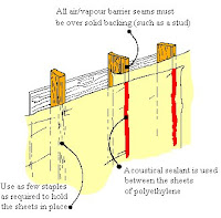
  • Acoustical sealant, does not harden or form a skin and is used for sealing joins in the air/vapour barrier.
  • Polyurethane foam is a special type of material useful for sealing large gaps around rough openings or along sill plates.


Weatherstripping is used to control air leakage at joints where two surfaces meet and move such as opening windows and doors. Weatherstripping is available in compression types, wedging types and magnet types. Good quality windows and door units are supplied with quality weatherstripping materials and are tested for air leakage rates. One should select units which have been tested and shown to have air leakage rates of less than 1/2 cfm per foot of sash length (0.80 litres per second per metre).

Joining Air-Vapour Barrier Layers

Polyethylene sheets are used for the air/vapour barrier. It is essential, in an energy efficient house, that the air/vapour barrier be continuous and all joints between sheets be sealed over solid backing. A non-skinning caulking such as acoustical sealant is used to seal between joints in the polyethylene. Because polyethylene is often handled roughly when being installed, 6 mil thick (0.150mm) sheets should be used. In addition to being more fragile, thinner polyethylene is much more permeable to air/vapour transmission than the thicker 0.150mm (6 mil) sheets.


The air/vapour barrier has another role to play in house construction. In addition to controlling air leakage, it prevents water vapour movement into the walls, ceilings or floors.


Air/Vapour Barrier Position


If vapour from the interior is allowed to enter an insulated assembly during cold weather, it could condense and form ice at some point in the wall. When the ice melts, deterioration of the insulation and structural components will occur over time. There is also a potential for supporting mold growth within the wall assembly which can cause indoor air quality problems. For this reason, the air/vapour layer must be located near the warm (or interior) side of ceilings, walls and floors.


Research has shown that as long as the air/vapour barrier is placed within the first one-third of the total assembly R-value (measured from the warm side), then no condensation problems will occur.


Foundations


Every building must have an adequate foundation to support it. In cold climates, foundations usually form an enclosure under a building - a crawl space or basement - although some (slab-on-grade) are built right on the ground. Controlling the heat loss through the foundation is very important. Contrary to popular belief, earth is not a good insulator and one-third of the total heat loss in a home can occur through an uninsulated basement.


Masonry or Concrete Foundation Walls


Exterior Foundation Wall Insulation

Cast-in-place concrete or block-type walls are the most commonly used in Canada. Insulating this type of foundation is best done on the outside if possible. The large amount of thermal mass in a masonry or concrete foundation is included in the interior volume of the house if it is insulated on the outside. As well, the foundation is less susceptible to frost damage and leaking. Rigid insulation or glass fibre sheets can be used. The above grade portion must be protected with stucco, treated plywood or similar rigid exterior finishes. Since masonry or concrete walls are quite porous, a polyethylene air/vapour barrier is added on the interior to eliminate any potential condensation problems with the completed interior walls. The exterior foundation insulation details shows the application of rigid insulation.


Interior Foundation Insulation

Most masonry foundations however, have been, and will continue to be insulated on the inside. A most important step is placing a moisture barrier of polyethylene on the inside of the wall from the exterior grade level to the floor. The wall interior is then insulated and sealed similar to frame wall construction. It is also possible to use rigid insulation, attach an air/vapour barrier, then finish the wall directly over it. The interior finish is difficult to attach through the rigid insulation - which must be 4 to 6 inches thick (100mm to 150mm) in order to have an R-20 value (RSI 3.5). If plastic rigid insulation is used, drywall which is mechanically fastened to the foundation wall must cover it. A 2 x 4 inch (38 x 89 mm) stud wall frame work spaced 1.5 inches (36mm) out from the foundation wall, as illustrated, can be insulated with R-20 (RSI 3.5) batt-type insulation products.


This provides the easiest and most economical route if a foundation wall must be insulated on the inside. The interior foundation insulation detail shows how this is best done to provide a well-sealed and insulated wall.


There are currently a number of products available from manufacturers which offer rigid interior foundation insulation systems. These systems each have their own methods for attaching both the insulation and the interior finish and offer an effective alternative to wood framing and batt insulation.

Pressure Treated Wood Foundation Walls


Wood Foundation Wall

Wood foundations can easily be made very energy efficient. Often called a 'PWF' foundation they can be constructed in almost any type of weather. A wood foundation must, however, be designed by a qualified engineer and constructed by competent builders who understand the importance of proper base preparation, handling techniques for pressure treated materials, the use of correct fasteners, drainage installation, backfilling techniques and sealing requirements. Because the foundation walls are an extension of typical wood frame construction, installing batt insulation and applying the air/vapour barrier is quite straight forward.


PWF Foundation Floors


Concrete Foundation Floors

The floor in a pressure treated wood foundation can be a concrete floor slab. Rigid Insulation should be placed under the foundation floor to a minimum insulation level of R-10 (RSI 1.7). A moisture barrier of at least 6 mil polyethylene (overlap seams) is required. A 3 to 4 inch (75 to 100 mm) layer of sand placed on top of the rigid insulation and the air/vapour barrier protects both during the floor pour and aids in proper concrete curing. Extra insulation to protect footings may be required for shallow footing depths as is often the case in bilevel or crawlspace foundations.


The floor in a pressure treated wood foundation can also be constructed of pressure treated wood. Pressure treated wood foundation floors are constructed using standard floor framing techniques on a gravel drainage bed. The installation of an effective moisture barrier on top of the gravel drainage layer is very important (minimum 6 mil polyethylene sheeting with overlapped and sealed seams).The floor joist cavities can then be filled with standard batt, blown or loose fill insulations. An air/vapour barrier is then installed on top of the floor joists. The attachment of the floor and wall polyethylene sheets is another important step in creating continuity of the air/vapour barrier. Standard floor sheathing and finishes can then be applied.

Wood Foundation Floors

Polystyrene Foundation Walls


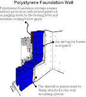
There are two basic techniques used to construct foundation walls using rigid polystyrene insulation. Some systems offer either polystyrene blocks or panels which use concrete and steel reinforcing placed into the cavities for structural support.


Other systems offer solid polystyrene panels using metal or wood studs for structural requirements. In either case, an interior polyethylene air/vapour barrier is applied and covered with a fireproof layer of drywall or plaster which must be mechanically fastened to the structural part of the wall. The outside must also be covered with a rigid material or parging to protect the polystyrene from mechanical damage and degradation from sunlight and soils.


Polystyrene Foundation Wall

Crawl Space Construction


Many homes have been built with partial depth foundations which are often called crawl spaces. Because the crawl space area under a home usually contains some mechanical services, insulating the foundation walls and floor is recommended to keep the temperature above freezing. A crawl space floor should be treated the same as an exterior wall, insulated and sealed from the house interior space. The crawl space walls can be insulated from the interior or exterior using standard foundation insulation methods. Perimeter insulation is then added as well to ensure that the crawl space retains more heat and is able to resist frost penetration. A moisture barrier, placed over the ground surface, is necessary to keep the space dry.


Crawl Space Construction


As well, summer ventilation should be provided by having outside air vents into the crawl space which can be opened in spring and closed in the fall. Any accumulated moisture can then be vented out during the summer months.


Slab-On-Grade Construction


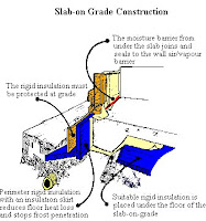
With this type of foundation the concrete slab is the combined foundation and finished floor surface. Rigid polystyrene insulation is used below the slab to lower floor heat loss. Perimeter insulation is also applied to control heat loss from the edge of the floor slab. An insulated skirt of rigid insulation extending down and away from the foundation wall around the entire perimeter will eliminate any potential frost problems, improve drainage and help further reduce heat loss.


Slab-On-Grade Construction


The polyethylene air/vapour barrier can be applied on top of the insulation, directly below the slab. A 3 to 4 inch (75 to 100 mm) layer of sand on top of the rigid insulation and the air/vapour barrier will protect both during the floor pour and aid in proper concrete curing. In order to provide continuity with the wall air/vapour barrier, the floor polyethylene layer must be placed so it can conveniently join to the wall layer at some point during construction.


To better anchor a slab-on-grade foundation, it can be attached to concrete piles. Large diameter holes of 8 to 12 inches (200mm to 300mm) are drilled 10 to 12 feet deep (3m to 4m) at intervals around the edge of the foundation. Reinforcing bars tie the thickened slab edge to the piles. In soils where drainage and frost is a problem, additional piles in the centre of the foundation may be required to prevent movement.

Tuesday, January 8, 2008

Site, Solar & House Planning (Part 2)

Room Layout and Traffic Flow


Traffic flow and stair location are integral parts of successful home layouts. The previous section on interior planning showed that stairs should be located centrally to the plans so that circulation to all spaces is direct and convenient. Traffic flow through the home should be as easy and simple as possible. Centrally located entries, as well as stairs, help in simplifying traffic flow in the home.


Room Layout

Traffic flow in individual rooms should also reflect this simplicity. Locate frequently used items convenient to the user - for example, closets and dressers in bedrooms should be close to the door, not on the other side of obstacles like beds.


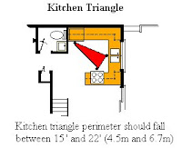
Kitchen Triangle

Consider how each room can be designed for ease of use, especially those work areas like kitchens and utility rooms. In the kitchen, the sink, range and refrigerator form the corners of the kitchen triangle and the total perimeter length should fall between 15ft and 22ft (4.5m and 6.7m). Millimetres and metres are the common SI system dimensions used for length measurements on plans.


Scale drawings and furniture should be used to analyze how each room works in your home. Make sure that the plan and rooms relate well throughout. In the enthusiasm of creating an energy-efficient home, don't overlook the functionality of the plan in terms of a family living space. A wide variety of good software programs are available which can help you develop your floor plans.


Many energy efficient home plans have horizontal and vertical openings between living spaces so that passively heated air is free to move about the space. In these types of plans, individual room design may be overshadowed by the impact of the entire space. This is important when considering traffic patterns and furniture placement and how the space appears visually from one area to another. Closed plans on the other hand, are subdivided into individual spaces. In these layouts, the rooms are separate. Less importance is given to the overall interior and visual impact.


Most homes are a combination of closed and open plans. Living, working and activity spaces usually have a degree of openness between them. The kitchen and eating may be combined, hobby and family areas joined, sun spaces and living areas can be linked, or dining and recreation spaces may occur together. Private spaces, such as bedrooms and bathrooms, constitute a closed part to every plan.


Designing for a Handicapped Occupant


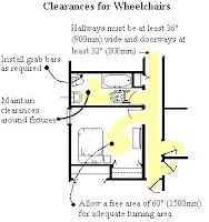
Clearances For Wheelchairs

Special consideration should be given to handicapped occupants of your home during the planning stages. The degree of handicap will of course govern how a plan and construction must be modified. Special hardware and doors, heights of countertops, levels of illumination and the elimination of stairs may be factors requiring consideration.


The most significant changes in planning occur when accommodating occupants requiring wheelchairs. The graphic illustrates some of the design criteria involved in making sure adequate manouvering room is left in the home.


On-grade entries can eliminate the need for exterior ramps and will provide much safer winter access. Hallways should be at least 36 inches (900mm) wide with clear access provided to doorways - small jogs or angles should be avoided. Any house plan can be easily changed in order to accommodate a person confined to a wheelchair.


Initial Planning Steps - A Summary


The key to a successful home design lies in the accommodation of the occupant's needs, wishes, tastes and lifestyles. In a home planning exercise, the following steps have to be considered.


  • Develop a list of spaces and their approximate required sizes.


  • Check that all group and individual needs are met (remembering that small children, elderly or handicapped occupants may have special needs).


  • Combine spaces and functions into 'multi-purpose' rooms or areas to conserve excess building area. Scale furniture should be utilized to determine if areas have enough room for circulation and your furniture pieces.


  • Establish the building shape you require - bungalow, bilevel, One and a half Storey, Two Storey, etc. A rectangular volume, oriented along an east-west axis, is most practical in a cold climate.


  • Using the selected building shape, arrange the interior spaces for ease of circulation, access to stairs and entries, proper zoning of working, living and sleeping areas, and interior/exterior relationships (to views, outdoor recreation areas, entries, etc).


  • Make sure openings (such as doors and windows) are properly located with respect to views, circulation (both interior and exterior), natural light and ventilation, and for passive solar access.


Quite often, little thought is given to areas like entries, bathrooms and hobby areas or concepts in window design with regard to function, interior-exterior relationships, or the potential for passive solar heat. Time spent during the initial planning stages can result in an energy efficient home truly tailored to your own family which will provide lasting economy, comfort and satisfaction.


Exterior Design


Exterior Styles


Exterior design should express the inner plan and lifestyle of the inhabitants. Unpretentious, informal and contemporary design frequently illustrates this concept better than earlier architectural styles. Many traditional styles were designed with massive stone or timber walls for structural reasons and to protect the family from the outdoors. Contemporary design tends to emphasize a lighter scale and interior-exterior relationship of spaces. Window and door openings unify interior and exterior activities, views and finishing materials.


Selecting a house design that fits your style of living and budget, meets your taste and is energy efficient, is difficult. But an energy efficient home operates because of proper design, orientation, construction and operation - the exterior 'cosmetics' applied afterward will not greatly affect energy use. It is personally satisfying, however, to live in a home that is pleasing in appearance.


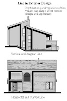
Line In Exterior Design

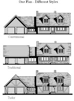
One Plan - Different Styles

Another Plan - Different Styles

As illustrated, convential homes can be transformed to different styles by using exterior finishing materials. Among popular North American houses seen today:


  • Colonial styles are characterized by formal, balanced design, a narrow siding or brick, shutters, small window panes, a columned entry and dormer windows.

  • Tudor styles show sharp gables, stucco and half-timber construction, bay windows, diagonal mullions and recessed doorways.

  • Spanish homes show low pitched roofs, white stucco walls, wide overhangs, curved archways, wrought iron details and darkly stained woodwork.

  • Modern style homes have developed out of an informal lifestyle. General characteristics include careful structure-site integration, open floor plan, shed roofs, larger glass areas, geometric forms and an honest display of finishing materials.

  • Contemporary housing has developed recently and is most often characterized by the ranch styles used with bungalow homes. The long, low roof with wide overhangs is a dominant feature - but the rambling development is not in keeping with the compact, energy-saving styles required in a low energy home.


The openings (doors and windows) and exterior finishing materials used on a home can be varied in style and applications to create different home characters. Notice in the illustration how combinations and variations of horizontal, vertical, angular and curvilinear lines can be used to emphasize height, width, depth, volume or mass. Windows especially contribute to pleasing exterior appearances. Uniformity in selection and placement are important in design although unique shapes or sizes, used discreetly, can lend an individualistic appearance to a home.


Roof Design


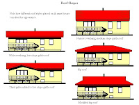
The roof is one of the strongest architectural elements of a home. A badly proportioned roof is very distracting. The shape of the roof does more to establish the character of the house than any other single feature. Trying alternate roof lines on a home can be an interesting exercise.


Roof Shapes


Adapting a Plan to Your Family


Existing Plan


It is difficult to find a home plan that is exactly what you have been looking for. That is because most houses have not been designed specifically for you, your family or your site. On the other hand, many people seem to be able to find a plan that is close to what they want, and any plan can easily be altered. One that you see in a newspaper, a building brochure or at a show home site may appeal to you in general. With a room change here or there, it may be the answer to your housing dreams.


For convenience in planning, you may want to draw your floor plan on paper at a scale of 1:50 - which means that every millimetre on paper equals 50mm in actual size or a scale of 1/4 inch equals one foot. If you use this scale when drawing, it will be easy to use scale furniture for planning and a draftsperson will readily be able to follow your ideas. It also saves time to have 'onionskin-type' tracing paper on hand so that you can trace proposed changes or alterations on it in pencil right over top of your original floor plans.


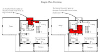
Making one or two changes to an existing plan is an easy modification. Simple internal changes could include removing or altering closets and storage areas, changing bathroom layouts, revising kitchen/eating arrangements, or altering entry locations. If this plan were used on a farm or acreage, the family may want to revise it as shown so that a better 'mud room' and air lock is provided at the most frequently used entry (through the garage).


Simple Plan Revision


Changing an Existing Plan


A more major interior modification could be made to change the entire character of a plan. Major internal modifications might include changing one or two bedrooms into work and hobby areas or increasing storage space. This floor plan shows a revised kitchen/livingroom area to make it a more open-type plan. Instead of isolating the living area from the kitchen/eating space, all three functions can occur together - just the 'closed-to open' plan alteration that may suit an active family.


Opening Out A Plan

Altering the exterior appearance also falls under this category. If you have a floor plan you like, coupled with an exterior design you don't, just remember that appearance is usually only skin deep. Relocating windows or doors, differing exterior finishes or differing roof lines can drastically change the exterior look. The exterior design section showed how the same basic plan could be used to create a number of 'different looks'.


Expanding an Existing Plan


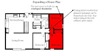
Few new home plans are conceived with the idea that one day the home might easily be expanded to meet additional needs. However, an expandable house may be the answer for a young couple with no children and limited finances. By initially planning for a home that can easily be added to at a later date, you can have a home in the end which meets the basic requirements for function, economy and individuality. Illustrated is a simple, expandable house plan. Two bedrooms are added as the family and their financial capabilities grow.


Expanding a Plan

Another approach to planning for expansion shows how the desired plan is only partially built initially. The rooms adopt their final use when the plan is completed - in this case, when the garage and entry section is added.


Planning For Expansion

It is difficult to build in the capability of adding to a basement- type foundation. Because of this limitation, additions are often constructed on crawlspace or slab type foundations. However, when completing your initial planning be sure to allow for future planned development. This includes water, sewer, electrical and heating needs so that the services are properly sized for any additions and can easily be connected in the future.


Adapting a Plan to Fit Your Site


Most energy efficient home designs show ideal elevations and site slopes. However, your site may be flat or have a north facing slope as opposed to the ideal south-facing situation. The basic rules of minimizing east, west and north windows still apply but the amount of south-facing glazing may have to be reduced for a home built on a north-facing slope. Site protection and unobstructed winter sun requirements still apply.


Different slope situations can also affect entries. A bilevel entry change shown is a possible solution to building this home on a flat site.


Altering An Entry

Proper orientation for views and solar gain may be another concern in siting. This plan is shown drawn again in a mirror image. Note how the space orientation changes. If you have selected a floor plan and suspect a reverse image would improve the layout on your site, hold the plan up to a mirror and evaluate the effect.


Reversing A Plan

The reversed image of this plan shows how each room orientation is changed.


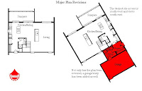
Adapting a plan for your site will most probably involve a combination of changes. This plan shows an example of adapting a plan for family considering this home for a rural site, with access from the south-west, and wanting an attached garage with mudroom. The revised plan could be as shown. A larger laundry/mudroom entry provides the link to the garage, with an airlock foyer and more coat storage space provided in the house itself (the plan was reversed to allow a view from the kitchen to the yard). In this case, the garage provides a good buffer against winter winds and the bedroom windows are oriented east of south for excellent morning light and passive gain.


Major Plan Revisions

Adapting a plan to your particular needs and site can vary from a simple position change to complex interior alterations and additions. Any plan you see on paper is just that - and changes are easy at that point. Even plans for premanufactured alternatives such as modular, sectional or package homes can be altered to a large degree. Partitions can be moved, doors and windows altered or finishes changed. If you visit a show home that appeals to you, find out where drawings are available. For a small fee, they too can readily be altered so that the resulting home will fit you and your family both now and in the future.